

John Henry
John Henry is the Technical Director at Trafalgar Fire. He has developed and introduced numerous innovative passive fire solutions in Australia, that save construction professionals millions while maintaining the highest safety standards.
This is just a snippet of the full article. To read the entire article, download the pdf today.
Introduction
Buildings must be compartmented into fire rated zones using fire resistant walls, floors and ceilings to prevent the spread of fire from one compartment to the next. However building services must be allowed to penetrate these fire barriers to allow for plumbing, electricity, data, communications, air-conditioning and ventilation. Therefore, a building designer should allow for the provision of service penetrations within their building design.
Traditionally, the fire stopping of service penetrations has been left to the last minute for the service trades to run around the site sealing up the holes and gaps around their services a few weeks before the occupation certificate (OC) is issued. This lack of design and planning, coupled with an focus on building certification has lead to large numbers of defective installations due to a lack of understanding of the concept of the passive fire penetration system.
Moving forward, the construction industry across most states and territories of Australia are introducing new legislation that requires higher levels of building design prior to the Construction Certificates (CC) being issued, and therefore building designers must start planning ahead and designing for passive fire.
This specification guide provides simple ‘compartment-by-compartment’ design rules and examples for how this can be done in a practical way to comply against the Deemed to Satisfy provisions of the National Construction Code (NCC).
This guide applies to Volume 1 of the NCC2022 for all types and classes of construction but will place focus on class 2 residential projects for most of the case studies and examples.
Building Code Requirements for Service Penetrations
The National Construction Code lays out the Deemed to Satisfy (DtS) compliance pathway for “openings for service installations” in clause C4D15. Whilst this clause does give a few options, the only recommended pathway for new buildings is to comply with part 2a) as well as Specification 1 of the NCC.
This clause requires service penetrations to be fire tested to AS1530.4-2014 IDENTICALLY to how they will be installed on site, and visa versa. This means that any installations on a site must be installed IDENTICALLY to how the penetration was tested in the laboratory conditions.
Minor variations to the penetration systems tested to AS1530.4 are only permitted when an accredited testing laboratory writes a formal report in accordance with AS4072.1 (referred to as ‘assessment reports’ or ‘formal opinions’).
The biggest misconception of AS1530.4 fire testing is that the test gives an inherent ‘fire rating’ to a product of material. This is not the case! An FRL is assigned to the full tested system, which comprises of the following items:

Therefore, from the very start of a building design these passive fire penetration systems should be front of mind, otherwise you risk specifying products that do not allow for a Deemed to Satisfy (DtS) penetration system to be installed which will lead to defects and potential life safety risks.
Design Strategies for Service Penetration Systems
The aim for the designer should be to reducing the number of holes in all fire barriers to simplify the documentation, compliance, sequencing, service separation, confusion and risk if defects on site. A good building designer should consider the following strategies:
Look into the different types and brands of fire Walls/floors/ceilings before specifying, to check if the fire barrier been tested with service penetrations systems
- Explore the most efficient way to compartment the building – Do the riser shafts need to be fire rated, or can the services be sealed floor-to-floor?
- Understand the spacings and clearance requirements between service penetration systems, to allow enough space above door headers and riser cupboards.
- Document the passive fire systems used up front by generating penetration registers, using documentation apps and platforms, using BIM and Revit models etc. This will help identify issues with the fire design early.
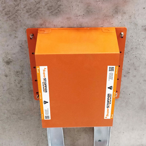
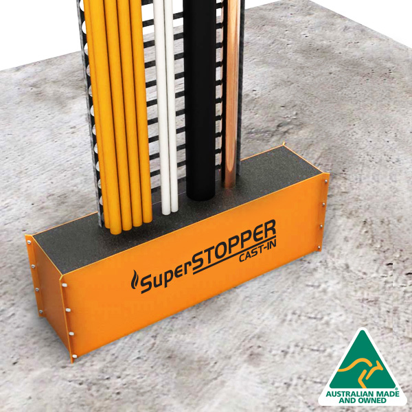
- Simplify the design with multi-penetration systems like the Trafalgar SuperSTOPPER range.
Refer to Trafalgar Fire’s “Fire Barrier” web page to see if the chosen fire barrier is compatible with penetrations:
Do I Need a Fire Rated Riser Shaft?
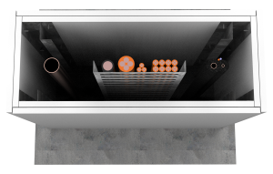
A riser (or riser shaft) is an enclosed shaft that runs up through a building to allow services to be routed easily through the building and return to a plant room, plant equipment, vent to atmosphere or connect to the street for example. Because the riser connects various fire compartments together, care should be taken to ensure that the fire compartments are maintained and separated appropriately.
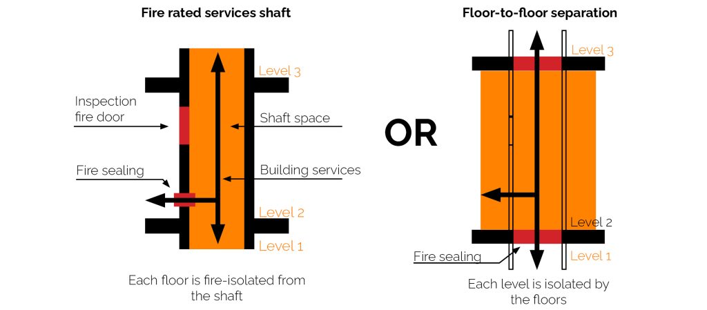
There are two ways to design for these scenarios:
Floor-to-floor separation where you fire-stop the services as they penetrate through each floor level, allowing for the riser shaft to be constructed from non-fire rated construction (cost effective, no fire doors needed etc), or
Fire Rated Riser Shaft which allows the services to pass through un-sealed (open) penetrations at each floor level, and encloses all services within a shaft with fire rated walls (and fire doors, access panels and garbage chutes) on each level. This is useful for large quantities of services, but note that services will still need to be sealed with a tested system as they penetrate the riser shaft walls on each level. The completion of service penetrations through shaft walls (or any walls) often requires access to both sides of the wall to install fire sealants, collars and service wraps. Provision of access is a must!
Each has their own benefits, however some Types/Classes of construction will trigger the use of a fire rated riser shaft under NCC section C.
Best Practice: Floor-to-Floor Separation
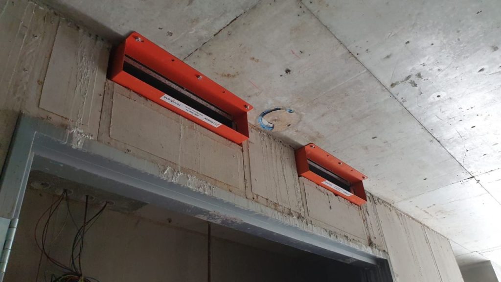
Common Defects Found in Fire Rated Riser Shaft Walls:
- Fire rated riser walls are rarely re-instated around the penetrations correctly.
- Access is always required to both sides of the shaft to install fire stopping
- Lots of services in a small footprint
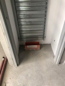
Common Defects Found in Fire Rated Riser Shaft Floors:
- High volumes of mixed services are can be tricky to plan for.
- Service separation often clash with wiring and plumbing codes
- Hard to estimate fire stopping costs
Cast-in Service Penetrations Systems Like the SuperSTOPPER & FyreCOLLAR Resolve Planning Issues:
- Accurately plan ahead for provision of services
- BIM models allow for easy planning and specification
- Reduce cupboard sizes

Specification of Service Penetration Systems
various types of fire rated walls, floors and ceilings that will be found across a typical Australian mid-high rise building designs with recommendations on what types of passive fire penetration systems to specify. This process is one that involves marking up a set of architectural plans with the locations of the all service penetrations and adding a unique identifier that will be used to track and document the systems used down to the installation sticker placed next to the penetration. There are Apps available to automate this process, but here we will show you how to step through the manual process.
Step 1 – Fire Compartment Plans
Generate the floor plans for each level and colour code the various fire walls by their required FRL. Most designers will also create a separate drawing with a list of the fire walls and their cross section details, wall system numbers and the AS1530.4 fire test or assessment reports for the actual wall. The compartment plans should also add the concrete slab thicknesses on each level and their required FRL.
Step 2 – Mark Up the Location of the Floor Penetrations or Fire Rated Shafts
If the riser shafts are designed to be fire rated, then the designer will need to highlight and label these as appropriate for the service trade or function of the shaft. The example below shows several fire rated shafts are marked up in green and clustered together for the garbage chutes, ducting and hydralic services:
The Trafalgar SuperSTOPPER range has BIM models available online that can be used if the designer is using REVIT families to design the building.
Step 3 – Create a Penetration Register
Using a simple spreadsheet or other platform, create a register of each of these penetrations. At this point you can add in additional columns that can be filled in by each service trade for each level.
At the design stage it is unlikely that the designer will have the specific information on the services however the more detail that gets included early will lead to a better and safer design. The service trades can get involved to assist by populating more specific details before building commences, and the builder or designer should double check for any changes to the schedule that might clash with an existing specification.
This penetration register can also be used to link test reports directly to the documentation and form the basis of compliance for occupancy certificates later in the project, as well as long term inspection and maintenance of the building over its life.
Step 4 – Complete the Plan Markups and Registers
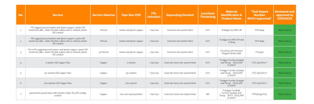
Once you have a format and register system that feels comfortable, continue through each level marking up the penetrations at the SOU walls, floor penetrations, ground floor retail/commercial and basement locations. See below example line entry.
Recommended Specifications Floor Penetrations
Concrete floors are almost always used to provide fire separation between every floor. For residential buildings, the floor slabs are commonly used to provide an FRL of 90/90/90 between apartments, but typically will have higher FRL’s (120/120/120) to separate carparks or commercial tenancies like shopfronts on the street level. It should be noted that loading docks and other special compartments (or classes/types of construction) might trigger the need for 3-4 hour FRL requirements which will require particular attention with specification and might require performance solutions to be included.
Many modern buildings now use steel decked slabs which provide a longer spans with less concrete, and provide some particular challenges when it comes to finding compatible service penetration systems.
Any penetrations and openings in the floors must be sealed in accordance with NCC C4D15 for integrity and insulation criteria of the FRL only (eg -/120/120) even if the fire barrier has an FRL with structural integrity. If the floor slab has a steel deck, consideration should be given to ensure that any passive fire penetration system specified is tested to interface with the various ribbed profiles of the deck. Traditionally the different service trades have their own dedicated riser cupboard to provide lockable, easy access for maintenance and addition of new services over the life of the building.