Introduction
It feels like yesterday, but most of us remember exactly where we were and what we were doing when mother nature reminded us on the impact she can have on the built environment across the ditch in Christchurch, New Zealand.
A major earthquake occurred in Christchurch, New Zealand, on Tuesday 22 February 2011 at 12:51 p.m. local time. The Mw 6.2 earthquake struck the Canterbury region in the South Island, centred 6.7 kilometres south-east of the centre of Christchurch, the country’s second-most populous city.
The damage to the building stock is well reported and the rebuilding of Christchurch is still ongoing more than 10 years later.
Fire and smoke walls were severely damaged and essential fire and other safety measures were rendered inoperable, which allows fire, post the event to destroy in inside of some buildings.
The building designers in New Zealand, Code officials and the like, just like elsewhere in the world previous after a major earthquake, had to STOP, assess what they learnt from observations post the “quake” and start designing & rebuilding more robust buildings and fitting them out with more seismic resistant walls, risers or service shafts, ceilings and the like.
This article deals specifically with services which pass through so-called fire rated and smoke proof barriers and looks at seismic testing protocols, any acceptance criteria for fire stopping systems, and discussed some work conducted by Trafalgar Fire of our Australian made SuperSTOPPER systems which part of our ongoing research and development in seismic performance of passive fire protection or fire stopping systems.

Desktop Literature Review and Google to the Rescue
Performance-Based Seismic Design Guidelines
The literature review unearthed the following performance-based seismic designed guidelines:
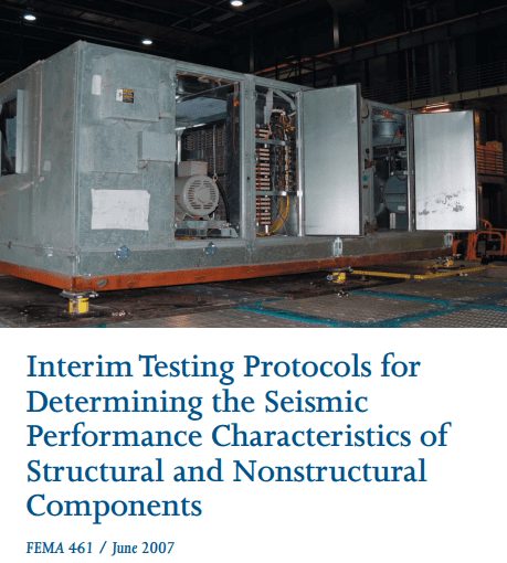
– FEMA 461
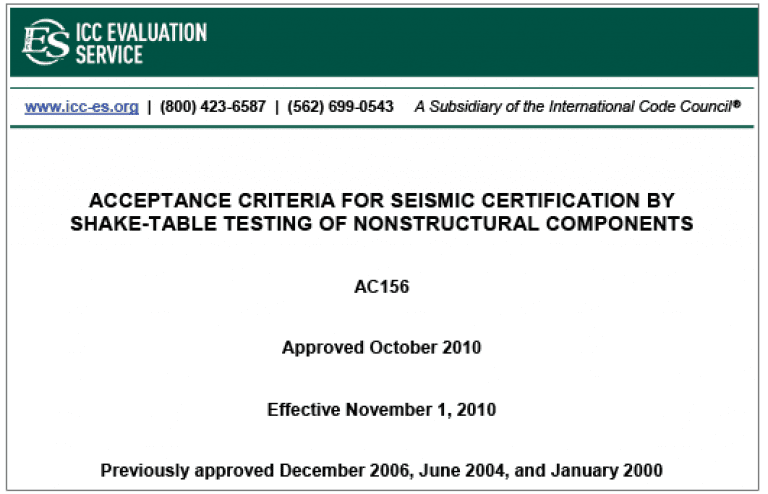
– ICC-ES AC156
– ASTM E3037

Shake-Table Testing Design Variables
We asked a lot of questions from the seismic design community, especially in New Zealand where the appetite for seismic product performance was rife.
Sadly, everybody had a different approach to seismic design and what test data they thought would be useful if Trafalgar was to commission independent seismic testing.
The design variables we identified were:
- Displacement or amplitude of seismic movement measure in mm
- Movement Direction, up and down and most important out of plane movement of the service relative to a wall for example
- Acceleration of movement
- Frequency of movement in cycles per minute or seconds; the latter being measured in Hz
We were about to step into a new space we knew very little about. We had to now decide what movement cycles we should subject our firestopping systems to.
From first principals, we knew that whatever fire stop system we used, it would need to be compressible or somehow allow for up and down movement, but the out of plane movement was the biggest concern, as the services will have a tendency we thought, to pull the fire stopping out of the wall.

Trafalgar Seismic Testing
We chose our initial testing to be conducted in New Zealand and chose Holmes Solutions in Christchurch.
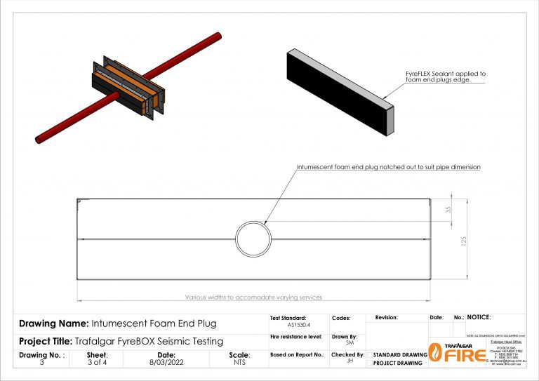
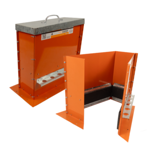
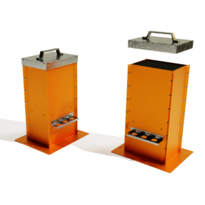
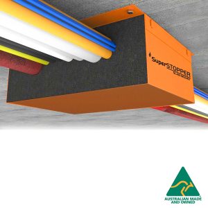
Some prominent seismic consultants in New Zealand gave us their wish list for the testing parameters and we decided to start our research and development program with our Trafalgar SuperSTOPPER systems. These are a metallic box incorporating high performance graphite intumescent material, positioned centrally inside the internal perimeter of the box along with graphite impregnated foam inserts or end plugs for the end of the box. These were developed for passive fire protection of services and Trafalgar Fire have several patented applications for what we call SuperSTOPPER. The services run through the box, and the ends are sealed around the services passing through the box with the smoke, acoustic and airtight foam inserts of end plugs.
What services do we use?
How much will the foam end plugs get damaged by movement? How much movement?
Will the foam end plugs be pulled out by the services when they move?
Will the SuperSTOPPER assembly be capable of maintaining fire resistance and limit the movement of smoke post a seismic event?
What magnitude of earthquake?
This is going to be interesting and fun, but remember fellow Trafalgar Engineers, its COVID and money is not plentiful after months of diminished sales.
Can we get some Government funding for what Trafalgar thinks is leading edge research and hopefully providing results which will benefit the Built Environment?
Oops, we cannot go to New Zealand to do the installation due to COVID restrictions. So lets hope we find a laboratory that can do the installation and run the tests without us being present.
Stage One – Seismic Testing of Trafalgar SuperSTOPPER
Some of our Trafalgar SuperSTOPPER 550 x 125mm boxes were sent to Holmes Solutions in New Zealand and Stage One of our Seismic journey started in 2021.
The Holms Solutions’ shake-table assembly and control equipment allowed us huge scope to experiment on the seismic performance of our Trafalgar SuperSTOPPER.

Preliminary Seismic Testing – The Ad-hoc and Unreported Initial Trials
We had no idea if the foam ends plugs, which form an integral part of a Trafalgar SuperSTOPPER would pop out, tear or what would happen to them once the shake table did it’s thing. This is we guess why we call these experiments research and developments.
We wanted to know if the Trafalgar SuperSTOPPER did fail or perform poorly, at what displacement or movement amplitude, at what speed or frequency of repeat movement cycles.
We made an executive decision to use our FyreFLEX acrylic fire sealant around the perimeter of the foam end plugs to help them stay in place. We did not put any sealant around the metal pipe service or on the joints where the foam is cu,t to allow fitting with an existing service in situ.
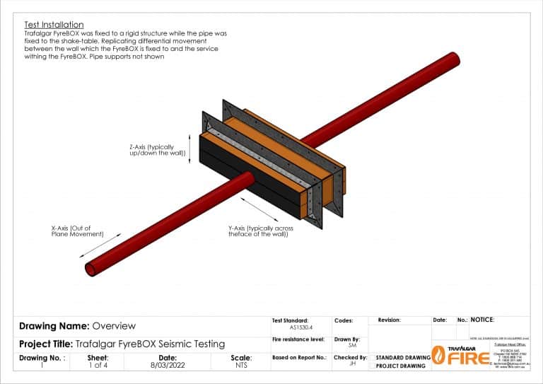
Testing was conducted uniaxially, that is in one direction at a time or in other words in the X, Y & Z axis (up and down, side to side and out of plane relative to a wall for example) individually, one at a time.
Results from the Preliminary Seismic Trials
– All conducted using the Same Trafalgar SuperSTOPPER Specimen
Slow acceleration 0.5Hz – 30 cycle per minute
- 20mm right and 20mm left (overall displacement of 40mm) – looked fine
- 20mm up and down – again looked fine
- 20mm out of plane – again looked fine
Repeat at 30 and then 50mm – No significant change except in up and down as pipe was hitting on top and bottom of SuperSTOPPER body as the internal dimension of model tested on has 125mm clearance and with a pipe of 50mm this only allow for 30mm nominal movement before interference. This caused some minor cracking or tearing of the foam.
We were happy with the preliminary trial results and this gave us the confidence to push the envelope and go for broke on a new identical specimen with serious simulated seismic activity and to have the results formally reported, for us to publish.
Stage One Formal Test Program
The following testing variables were used in the stage one formal test program:
Displacement Amplitude:
50mm (100mm total)
Movement directions:
X Axis – out of plane movement ( In and Out)
Y – side to side movement
Z – up and down movement
Frequency or Acceleration:
Frequency of 2.5 Hz (1 Cycle every 0.4s)
Acceleration Amplitude of 1.26g
Velocity Amplitude of 785mm/s .
So, what is next? Stage Two, Three et al
-

-
SuperSTOPPER® Cast-In Retrofit
- Select options This product has multiple variants. The options may be chosen on the product page
-
-
-
SuperStopper Cast-In Bambino: Compact Fire Protection for Smaller Spaces
- Select options This product has multiple variants. The options may be chosen on the product page
-
-
-
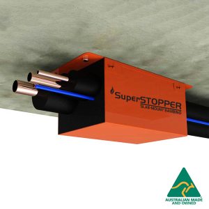
SuperSTOPPER® Slab-Mount
- Select options This product has multiple variants. The options may be chosen on the product page
-
Conclusions and Thoughts Post Stage One of Seismic Testing
We need to validate a whole system, that being, services in a wall or preferably a whole room enclosure with all of our Trafalgar fire stopping systems installed.
We are comfortable that the mounting flanges for the SuperSTOPPER Maxi system will spread the load and secure the box adequately in a wall and the overall results should be similar to those observed in the stage one seismic testing.
Probably the biggest concern for an overall system is the wall to concrete slab interface. Our research suggests that current fire rated wall constructions can provide no more than 5 to 10mm of out of plane movement without serious damage to the wall itself. There are some new innovative and patented Australian designed head of wall systems that have showed outstanding results in full scale seismic testing, which may help solve this problem
It would be nice to do triaxial testing; that this movement simultaneously in the X,Y & Z orientations, but the out of plane results and the nature of the compressible foam end plug inserts suggest to us we will see nothing different to the Stage One uniaxial seismic testing we have already performed.
We need to do some different service types, perhaps a cable tray and cables, but again we are confident this will do well too.
Fire testing post seismic testing, just ticks a box, pardon the pun, as we know having looked at the Stage One Seismic minor damage to the Trafalgar SuperSTOPPER, that any post seismic fire test would be successful.